Scope
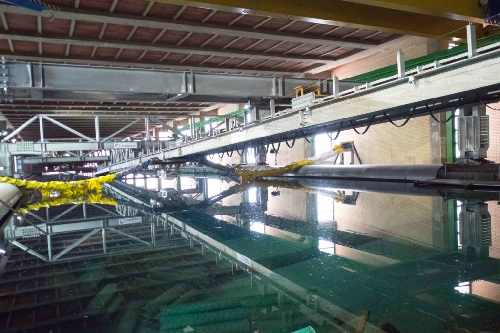
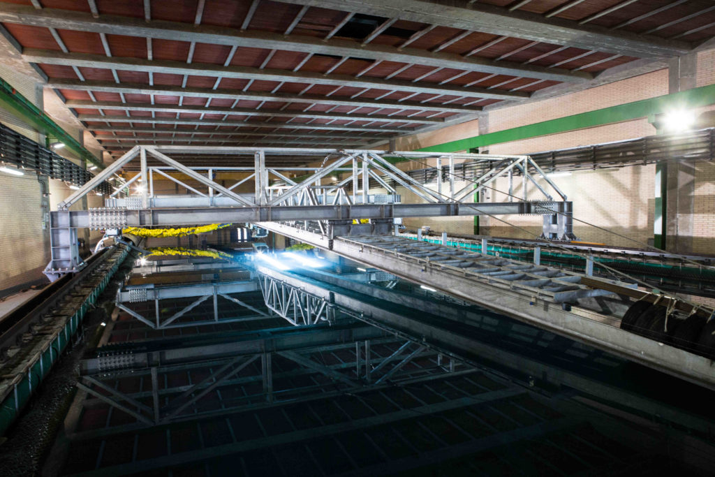
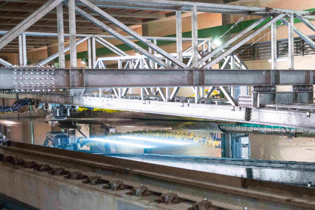
| The High Speed Ditching Facility (HSDF) was built to perform water entry tests with a horizontal velocity component up to 48 m/s with a vertical/horizontal velocity ratio in the range from 0.03 to 0.05. The facility was designed by Alessandro Iafrati and built during the EU-funded FP7-SMAES project and it was further developed and extended in its potentialities during the H2020-SARAH project. The facility makes it possible to test plates, bodies, or structural components in conditions close to those occurring during the aircraft ditching event. It is composed of a guide, 64 m long, suspended over the Umberto Pugliese towing tank by five bridges. The guide can be rotated to achieve different vertical/horizontal velocity ratios. The specimens to be tested are firmly connected to the acquisition box towed by a trolley running along the guide. The acquisition box and the specimen can be rotated to allow the impact at a pitch angle in the range from 4 to 16 degrees. The trolley is accelerated by a catapult composed of a total of 8 elastic cords. The cords are attached to a U-shaped bar which embraces the trolley and accelerates it to the final speed. Shortly before the impact point, a braking system acts on the U-shaped bar so that the trolley is left free to impact the water. The total mass of the system composed by the trolley, acquisition box, and specimen is between 850 kg and 900 kg thus making the velocity reduction during the test generally negligible (less than 1%). When the leading edge of the specimen arrives at the still water level and touches the water, the front faces of the specimen and of the acquisition box impact the water and the velocity drops sharply; next, a damping system absorbs the remaining energy. The test velocity is controlled within +/- 0.5 m/s by adjusting the release point of the catapult and compensating in this way the loss of strength of the elastic cords. The use of the elastic cords to accelerate the trolley does not allow a precise control of the test speed and thus a careful assessment of the test repeatability was conducted soon after the installation. The onboard acquisition system can acquire up to 40 channels at 200 kS/s. Measurements can be done in terms of accelerations, pressures, loads, and strains. The measurements are supported by the underwater movies done by a high-speed camera operated at 3000-5000 fps, depending on the specific test conditions. |
Main characteristics
| Horizontal Test Speed (max) | 48 m/s |
| Vertical/Horizontal velocity ratio | 0.03-0.05 |
| Specimen size (typical) | 1200 mm (L) 650 mm (W) |
| Available measurements | Loads, Pressures, Strains, Accelerations, Underwater visualization |
| Maximum number of channels and sampling rate | 40 at 200 kS/s |
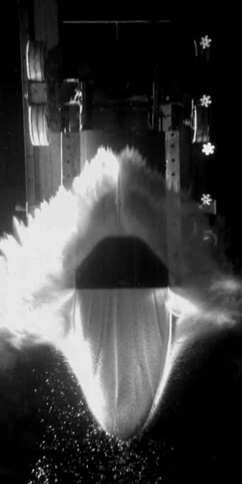
Underwater picture of the Dassault specimen. The specimen is made of a skin in Carbon Fiber Reinforced Polimer which is internally reinforced with frames and stringers, typical of small passenger aircraft. The test is performed at 46 m/s horizontal velocity, vertical velocity of 1.5 m/s and pitch angle of 6 degrees.
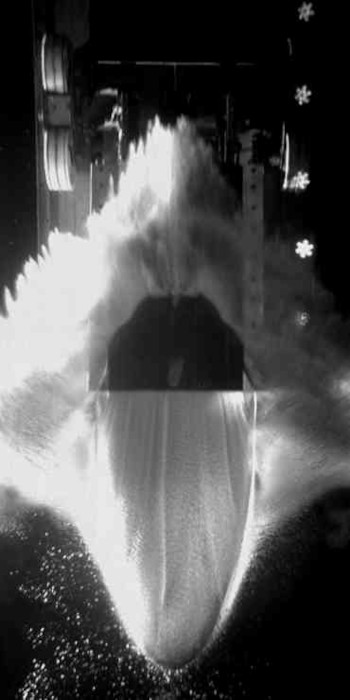
The picture refer to the second test of the Dassault speciment performed at the same conditions of the first tests but at 9 degrees pitch angle.
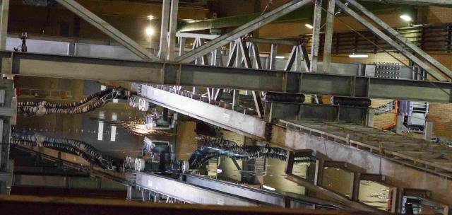
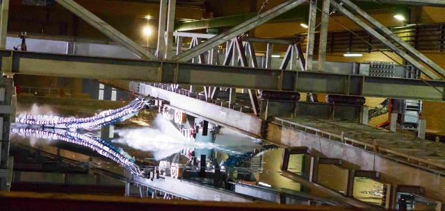
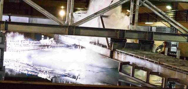
Underwater view of a test on double curvature specimen
The movie shows the development of cavitation and ventilation phenomena during the water impact of a double curvature specimen mimicking the rear shaper of a cargo aircraft. Impact conditions: 35.7 m/s horizontal velocity, 1.34 m/s vertical velocity, 6 degrees pitch angle
Pressure records
The movie displays the time histories of the pressure measured by probes located at the rear of the double curvature specimen. The time line is synchronized with the images at the side and underwater. The movie shows the pressure peak due to the first impact, the sharp drop to the vapor pressure value concurrent with the passage of the cavitation bubble, and the pressure rise associated with the ventilation occurring when the cavitation bubble reached the trailing edge and gets in contact to the ambient pressure.
Water impact of a structural component – Time histories of the forces
Water impact of an aluminum component mimicking the aircraft structure. The movie highlights the deformation of the structure which revels the internal reinforcement made of stringers and frames. In the upper part, the time history of the normal forces acting at the rear and forward position are drawn together with the total normal force. Test conditions: horizontal velocity 48 m/s, vertical velocity 1,6 m/s, pitch angle 6 degrees.
Water impact of a structural component – Time histories of the longitudinal strains
The movie shows the same test but in this case the time histories of the strains measured by gauges located along the midline of the specimen are displayed.
Contact information
| Scientific point of contact | Silvano Grizzi | +39 06 50299 253 |
| Technical point of contact | Flavio Olivieri | +39 06 50299 276 |
Location
| Rome HQ | Via di Vallerano 139, 00128, Rome, Italy |